The Context
The aim is to produce an overview of the analysis and design stages of a UML project. So we will introduce the main UML concepts,
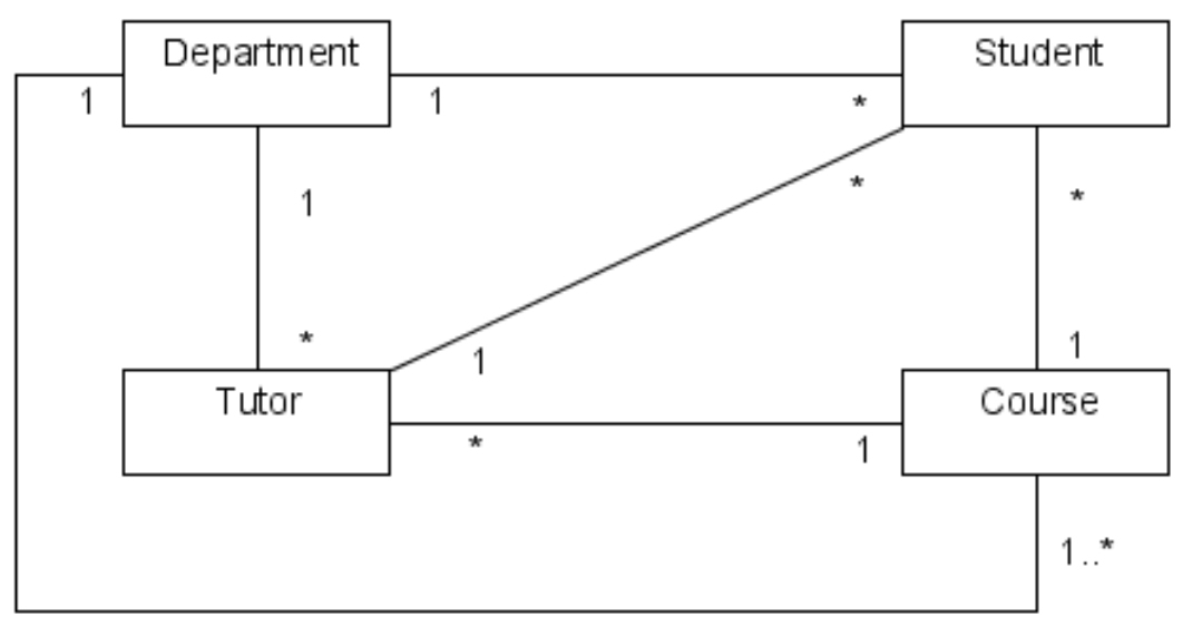
Class diagrams.
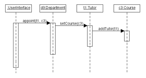
Sequence diagrams.
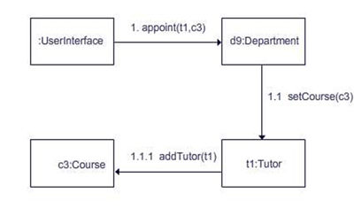
Communication diagrams.
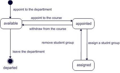
State diagrams.
This is not a detailed treatment but only an overview to show how these diagrams relate to each other.